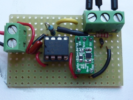
As part of my Arduino Power Controller project, I ordered and received the PCBs for the Circuits@Home boost converter utilizing the Texas Instruments’ TPS61240 chip. My SMD soldering experience is close to non-existent, but I recently acquired a Hot Air SMD Rework Station from SparkFun. That made soldering the converter chip possible for a mere mortal. After building the boost converter module, I built a new Arduino power controller board utilizing the module (picture below).
Because the TPS61240 isolates the output load when the chip is disabled, I did not need the MOSFET switch that I used in the prior Power Controller board. As well as having that advantage, the shutdown current for the TPS61240 chip is very low. I measured about 1.5 uA current draw of the entire power controller board when the PIC was asleep and the boost converter was disabled.
The power controller was built on a SB300 perfboard (cut with a Dremel to reduce its width). I’ve found these to be inexpensive and effective PCBs for building one-off projects.
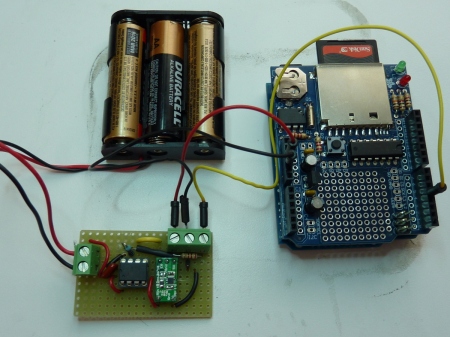
Below is a picture of the power controller in use controlling an Arduino with a Data Logging shield.
In this application, the Power Controller periodically applies power to the Arduino + data logging shield. While powered, the Arduino can read sensors, read the real-time clock on the shield, and then store the data on the shield’s SD card. After doing so, the Arduino raises the power-down line back to the Power Controller and the controller removes power from the Arduino. Multiple months of battery life can be achieved with this arrangement.
For the past month I have been measuring battery drain-down using the prior version of the Power Controller and a similar Arduino + data logging shield load. That version of the Power Controller used a less energy-efficient boost converter. Measurements on battery drain-down indicate that battery life should live up to the calculations presented in the prior article.
NOTE: A commercial product is now available from Adafruit that performs this power controller task. See the Adafruit TPL5110 Low Power Timer Breakout product.


November 12, 2012 at 12:24 am |
Excellent blog. I have a very similar problem I would like to solve and this looks like a very promising solution – although I haven’t managed to locate the PCBs from the batch production link provided by Circuits@Home yet, but I will have another look later.
How has your Power Controller been performing?
November 12, 2012 at 7:36 am |
Well, it worked great during testing, but I’ve been off on other projects and haven’t really deployed it for long-term use yet.
March 12, 2013 at 9:00 am |
[…] I will not have any worries about sufficient battery voltage to turn on the MOSFET. This links to my post describing the power controller I built using this […]
December 7, 2015 at 10:04 am |
Hey Alan, your blog is really helpful for me, as an absolute beginner in electronics. Big thank you. I just wanted to share this find as Oleg doesn’t sell the boost converters you are talking about here anymore, but this looks very similar: https://mozzwald.com/shop/tps61240-3-3v-to-5v-boost-converter-breakout-v2
December 7, 2015 at 11:38 am |
Good find! Another choice might be the Adafruit PowerBoost: https://www.adafruit.com/products/1903 . However, when it is disabled, the current draw is about 11.4 uA, which is higher than the amount of draw for a converter using the TPS61240 chip.
May 1, 2016 at 1:02 pm |
Nice idea.
I had little different one and I don’t know if it is completely bad one.
My idea was to build logger using just some ATmega chip (perhaps 3.3v, 8MHz), burn arduino bootloader and program, connect oscilator, step-up converter to provide power from two AA bateries and attach SPI, RTC and sensors to it. I guess this will remove nearly all parts with high power consumption (as power on LED) and Arduino can be put into sleep mode. I don’t have Arduino yet, but I’m going to try, if I can make temperature logger that can survive for weeks or months unattended and the way to “download” data would be likely only SD card exchange. I have not studied ways how to wake up arduino (8s sleep or using RTC) yet, but I’m going to try it. Thanks for inspiration or perhaps plan B.
August 9, 2016 at 9:22 pm |
[…] thorny issues there wrt multiple re-starts of the SD library. You can extend that strategy and cut power to the entire logger. However some of my builds use interrupts from both the sensors and the RTC, […]